
The fundamental mechanical paradox in orthopedic surgery lies in the relationship between rotational speed and cutting force. Low-speed drilling is clinically necessary to preserve bone viability and prevent tissue damage. However, operating at lower revolutions per minute (RPM) causes an exponential increase in the thrust force and resistance required to penetrate dense cortical bone. When a surgeon applies downward pressure, standard motors often stall or skip, compromising surgical precision.
Surgical facilities must equip operating rooms with power tools that prevent thermal necrosis without sacrificing mechanical reliability. Overheating bone tissue leads to irreversible cell death, which directly causes implant failure or delayed union. Surgeons need instruments that maintain a steady, slow rotation without requiring excessive manual force. Modern orthopedic power tools solve this exact problem through advanced electromechanical engineering. This guide breaks down the internal mechanics that allow an Electric Bone Drill to maintain steady low-speed rotation under heavy loads.
Clinical Thresholds: Low-speed drilling (typically 250–800 RPM depending on the procedure, such as hip reaming vs. implantology) is the industry standard for minimizing thermal necrosis and preserving osteocyte health.
Electromechanical Solutions: Steady low-speed rotation is achieved through a combination of Brushless DC (BLDC) motors, planetary gear reduction, and closed-loop electronic feedback systems (PID controllers).
Power Stability: The performance of a rechargeable orthopedic power drill at low speeds is heavily dependent on battery discharge curves and internal voltage regulation.
Procurement Focus: When evaluating surgical drills, decision-makers must prioritize trigger sensitivity, torque-to-speed ratios, drill bit compatibility, and the tool's resilience to repeated autoclave sterilization cycles.
Establishing a steady low speed is a non-negotiable requirement for specific orthopedic and maxillofacial procedures. When surgeons prepare a site for an implant or drive a heavy reamer into the medullary canal, the cutting tool must remove dense material efficiently without binding. If the rotation fluctuates, the surgeon loses tactile feedback. Inconsistent speeds cause the drill bit to catch against the bone cortex. This binding forces the operator to apply more manual pressure, which increases the risk of micro-fractures or accidental plunging once the cortex is breached. Success in these procedures relies entirely on the tool's ability to deliver constant torque at low RPMs.
Tactile feedback is the primary diagnostic tool a surgeon uses while drilling. The vibration and resistance transmitted through the handpiece tell the operator whether they are cutting through hard cortical bone or softer cancellous bone. When a drill stalls or surges unpredictably, this feedback loop is broken. A reliable power tool must act as a transparent extension of the surgeon's hand, maintaining a steady RPM regardless of the varying densities encountered along the drill path.
Bone tissue is highly sensitive to temperature changes. Clinical studies establish a strict temperature threshold for bone viability. Keeping bone temperature below 47°C is mandatory. If the temperature exceeds 47°C for more than one minute, the proteins within the bone begin to denature. Sustained high-speed friction causes irreversible osteocyte death. This cellular destruction leads to a zone of dead bone around the surgical site, which prevents osseointegration and ultimately causes implant loosening or failure.
To prevent thermal necrosis, surgeons rely on specific RPM ranges tailored to the surgical application. Heavy reaming procedures typically require speeds between 250 and 350 RPM. Delicate implant site preparation in maxillofacial or dental surgery operates safely between 400 and 800 RPM. These low-speed parameters stand in stark contrast to the upper limits of 1,100+ RPM used for entirely different tasks, such as driving K-wires or using oscillating saws. Maintaining these specific low-speed ranges ensures the cutting flutes shear the bone cleanly without generating excessive frictional heat. External irrigation with sterile saline is often used in conjunction with low-speed drilling, but irrigation alone cannot compensate for the massive heat generated by a drill spinning too fast.
The mechanics of drilling involve an inverse relationship between rotational speed, feed rate, and thrust force. Feed rate refers to the distance the drill bit advances into the bone per revolution. At high speeds, the bit takes many small cuts per second, requiring very little downward thrust force from the surgeon. At low speeds, the bit takes fewer cuts per second. To maintain the same overall penetration rate, the surgeon must push harder. This increased thrust force demands significantly higher torque from the motor to keep the bit turning.
Standard drill bits often rely on high-speed rotation to minimize the required thrust force. When surgeons use specialized, aggressive-flute bone bits designed for low-speed cutting, the cutting edges bite deeply into the bone. This deep engagement creates massive rotational resistance. If the surgical handpiece lacks sufficient torque, the motor will stall. Therefore, an effective electric bone drill must generate enough rotational force to overcome this resistance, allowing the aggressive flutes to sheer the bone without stopping. The relationship is governed by basic physics: Power equals Torque multiplied by Angular Velocity. If the Angular Velocity (RPM) is intentionally kept low, the Torque must be exceptionally high to deliver the necessary cutting power.
The foundation of steady low-speed rotation begins with the motor architecture. Traditional brushed motors rely on physical carbon brushes pressing against a commutator to reverse the electrical current. This physical contact creates friction, generates heat, and causes micro-fluctuations in speed as the brushes wear down. Modern surgical power tools eliminate this problem by utilizing Brushless DC (BLDC) motors. The absence of physical brushes completely removes friction-based speed variations, allowing for a remarkably smooth rotation profile.
Instead of brushes, BLDC motors use a stationary set of electromagnets (the stator) and a rotating permanent magnet (the rotor). An electronic controller dictates the exact timing and sequence of the electrical current sent to the stator coils. This precise electromagnetic sequencing delivers consistent, high-torque power even at very low RPMs. Because there is no physical drag inside the motor, the power delivery remains perfectly linear. Many high-end surgical drills utilize slotless stator designs, which eliminate "cogging torque"—the jerky, magnetic hesitation felt in standard motors at low speeds. This ensures the rotation remains fluid even when operating at 100 RPM.
Even the most advanced BLDC motors naturally operate efficiently at high speeds, often spinning internally at 10,000 to 20,000 RPM. To achieve the low speeds required for bone preservation, the tool must mechanically convert high-speed motor output into low-speed, high-torque drill bit rotation. This conversion is handled by a planetary gear reduction system. A planetary gearset consists of a central sun gear, multiple planet gears surrounding it, and an outer ring gear.
As the motor turns the sun gear at high speed, the planet gears rotate against the stationary ring gear. This configuration drastically reduces the output speed while simultaneously multiplying the torque. Evaluating gear ratios is a critical step in surgical tool design. A high gear reduction ratio (such as 16:1 or 64:1 depending on the attachment) minimizes motor strain during dense bone penetration. Unlike standard spur gears that place all the mechanical load on a single gear tooth, planetary systems distribute the massive thrust forces across three or four planet gears simultaneously. This load distribution allows the tiny gearbox inside a surgical handpiece to survive hundreds of pounds of axial force without stripping teeth.
Mechanical gearing alone cannot prevent a drill from slowing down when it hits a particularly dense section of cortical bone. To maintain a truly steady speed, the tool requires active electronic management. Closed-loop Electronic Speed Controllers (ESC) provide this capability. Microprocessors inside the handpiece use Hall effect sensors to monitor the exact position and rotational speed of the motor in real-time.
These microprocessors utilize Proportional-Integral-Derivative (PID) control loops. When the drill bit encounters sudden resistance, the RPM naturally tries to drop. The Hall effect sensors instantly detect this drop and send a signal to the PID controller. The controller calculates the exact amount of additional power needed and automatically draws more current from the battery. The Proportional band reacts to the immediate drop in speed, while the Integral band ensures the RPM returns exactly to the surgeon's intended setpoint. This process happens in milliseconds. The result is a tool that powers through dense bone without any perceptible change in rotational speed, completely eliminating stalls.
Orthopedic Drilling Speed Parameters
Procedure Type | Recommended Speed Range (RPM) | Primary Clinical Objective |
|---|---|---|
Heavy Intramedullary Reaming | 250 - 350 | Maximize torque, prevent canal overheating, clear large bone debris. |
Dental / Maxillofacial Implantology | 400 - 800 | Precise site preparation, preserve osteocyte viability for osseointegration. |
Standard Cortical Tapping | 100 - 250 | Thread creation without stripping the surrounding bone structure. |
K-Wire Insertion | 1,000 - 1,200+ | Rapid penetration of cortical bone to prevent wire bending or deflection. |
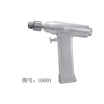
The interface between the surgeon and the machine dictates the clinical outcome. Assessing the linearity of the variable speed trigger is a primary evaluation metric. A high-quality variable control surgical drill provides a perfectly linear response; pulling the trigger 10% delivers exactly 10% of the maximum speed. Advanced models utilize Hall-effect triggers rather than physical potentiometers. Hall-effect triggers use magnets to measure the trigger pull distance, meaning there are no moving electrical contacts to wear out or fail during harsh sterilization cycles.
Ergonomic design plays a massive role in operational success. Surgeons must make micro-adjustments to the RPM while simultaneously applying downward thrust force. If the trigger spring is too stiff, or the handpiece is poorly balanced, hand fatigue sets in rapidly. Fatigue degrades tactile feedback, making it difficult for the operator to sense the transition from cortical to cancellous bone. Evaluating the physical design ensures the surgeon maintains precise pace alteration without physical strain. Some models also utilize adjustable speed-limiting knobs or dials, allowing the surgeon to set a hard ceiling on the RPM to ensure a fully depressed trigger will not exceed the safe threshold for the specific procedure.
The capability of the ESC to draw extra current on demand relies entirely on the power source. Comparing Lithium-ion (Li-ion) to Nickel-Metal Hydride (NiMH) battery chemistries reveals stark differences in performance. Older NiMH batteries suffer from voltage sag; as they discharge, their maximum power output drops. This means a drill might perform perfectly at the start of a surgery but stall easily an hour later when the voltage drops below the threshold required by the PID controller.
A modern rechargeable orthopedic power drill utilizes advanced Li-ion battery packs built with high-discharge cells. Li-ion chemistry provides a remarkably flat discharge curve. The battery delivers its maximum rated voltage and peak current consistently until it is nearly depleted. This flat discharge curve prevents RPM drop-off as the battery drains during lengthy procedures. Furthermore, integrated Battery Management Systems (BMS) inside the pack communicate directly with the drill's ESC, ensuring the motor always receives the exact amperage required to maintain steady low-speed rotation under heavy loads without overheating the cells.
The physical architecture of the drill impacts its internal mechanics. Cannulated drills feature a hollow channel running entirely through the center of the handpiece. This allows surgeons to pass Kirschner wires (K-wires) or guide pins directly through the tool. However, this internal geometry impacts the integration of gearing and motor placement. The motor rotor and planetary gears must be built around this central hollow tube, which changes the rotational inertia and often requires larger external dimensions.
Non-cannulated designs do not have this restriction. They can utilize solid, centrally aligned motors and tighter gear clusters. When evaluating low-speed performance, buyers must weigh the trade-offs in weight and balance. Cannulated models offer superior procedural versatility for trauma cases, but non-cannulated models often provide a lighter, more balanced profile for dedicated reaming or drilling tasks. The internal seals on cannulated models also require more rigorous maintenance to prevent bio-burden from entering the motor housing during surgery.
Operating room equipment must survive brutal sterilization environments. Repeated autoclave cycles subject the tools to high heat (typically 134°C) and pressurized moisture. This environment poses a severe risk of degrading the microprocessors, Hall effect sensors, and ESC components responsible for low-speed regulation. If moisture breaches the housing, the PID controller will fail, resulting in erratic speeds, sudden stalls, or complete motor death.
Mitigating this risk requires strict evaluation of the tool's physical construction. Facilities must look for IP-rated sealing, encapsulated electronics, and hermetically sealed motor housings. Manufacturers often pot the sensitive circuit boards in specialized thermal epoxy to protect them from steam penetration. Outer housings made from laser-welded titanium or high-grade PEEK polymer offer superior resistance to thermal expansion and contraction. Hospitals must also enforce vendor-validated sterilization protocols, ensuring staff do not use unapproved chemical solvents or bypass the necessary drying phases of the autoclave cycle.
Even the best Li-ion batteries degrade over time. As a battery ages through hundreds of charge cycles, its internal resistance increases. This aging process prevents the battery from delivering the rapid spikes in peak current required by the ESC to maintain low speeds under heavy load. A degraded battery might show a 100% charge on the indicator, but under load, the voltage sags instantly, causing the drill to stall even if the motor and gearing are in perfect condition.
To mitigate torque loss, surgical centers must implement strict battery lifecycle management. Batteries should be tracked by charge cycles and internal impedance, not just calendar age. Selecting systems with built-in diagnostic indicators allows biomedical technicians to identify and retire weak battery packs before they fail in the middle of a procedure. Routine load testing ensures the power source remains capable of supporting the drill's anti-stall mechanisms.
Transitioning to advanced variable-speed equipment introduces human-error risks. Surgeons accustomed to older pneumatic systems or basic single-speed drills often develop a habit of over-applying thrust force. Because older tools lacked low-end torque, pushing harder was the only way to cut. Applying this same aggressive force to a modern, high-torque electric tool can cause the bit to plunge dangerously fast once it clears the dense cortex.
Mitigation relies on comprehensive hands-on vendor training. Training must focus on clinical best practices, such as initiating drilling at a low speed to establish the trajectory without causing thermal spikes. Surgeons must learn to trust the tool's active feedback system. By applying steady, moderate pressure and letting the variable control surgical drill's torque do the work, operators achieve cleaner cuts, reduce bone necrosis, and improve overall patient safety. The tool will automatically adjust its power draw to maintain the speed; the surgeon simply needs to guide it.
Maintaining steady low-speed rotation requires a sophisticated interplay of BLDC motors, planetary gear reduction, active electronic feedback, and proper surgical technique. When the equipment actively manages power draw to match physical resistance, surgeons can focus entirely on trajectory and depth control rather than fighting the tool. Procurement teams must prioritize documented torque retention, battery discharge stability, and robust electronic protection against autoclave damage.
Audit your current power tool inventory to identify devices with high stall rates during dense bone procedures.
Request trial units for in-vivo evaluation to test ergonomic balance and trigger linearity in a live setting.
Test the drill's anti-stall capabilities and feed-rate handling by driving aggressive-flute bits into dense bone analogs.
Review the vendor's Service Level Agreements (SLAs) to confirm turnaround times for battery replacement and microprocessor calibration.
Verify the specific potting methods and IP-ratings used to protect the internal electronic speed controllers from routine autoclave cycles.
A: Ideal speeds vary by procedure: 250–350 RPM for heavy reaming, 400–800 RPM for implantology, and up to 1,100+ RPM for K-wire driving and other high-speed applications.
A: It allows the surgeon to initiate and maintain low RPMs to reduce friction, while relying on high torque and specialized drill bit geometry to ensure efficient cutting without prolonged bone contact.
A: They lack closed-loop electronic feedback (PID controllers) and have insufficient planetary gear reduction to handle the exponentially increased thrust force required at lower speeds.
A: Modern Li-ion batteries offer flat discharge curves that sustain peak current for lengthy procedures, though exact times depend on the density of the bone and the torque demanded by the ESC.
A: Pneumatic systems rely on air-pressure regulation which can fluctuate under load, whereas modern electric systems utilize precise microprocessor control to actively adjust power draw and maintain steady RPMs.
A: Yes, modern devices use hermetically sealed, autoclavable housings to protect internal electronics, but facilities must strictly adhere to manufacturer IFUs to prevent premature degradation.


