
High-torque, low-RPM drilling applications require absolute mechanical stability. Operating a motor below its optimal speed curve without mechanical reduction introduces stalling, heat, and critical inaccuracies. Direct-drive systems struggle to maintain consistent torque at low speeds. Engineers and procurement teams must select gear reduction mechanisms that amplify torque and reduce speed without introducing backlash, spindle runout, or excessive vibration—critical failures in both aerospace manufacturing and medical device applications. This guide evaluates the primary gear reduction architectures, framing the technical trade-offs, implementation risks, and performance criteria necessary to engineer or select a highly stable Slow Drill system.
Ratio and Torque Correlation: Gear reduction ratios (ranging from 2:1 workshop retrofits up to 10:1, 13:1, or 20:1 heavy-duty configurations) mathematically dictate the inverse relationship between spindle speed reduction and torque amplification, establishing the baseline for drill stability.
Architecture Dictates Precision: Planetary gearboxes offer optimal torque density, while harmonic (strain wave) gears are required for zero-backlash, high-precision environments.
Vibration Isolation is Critical: In applications requiring a low vibration medical drill, gear meshing frequencies and alignment tolerances must be tightly controlled to prevent resonant vibration.
Thermal and Lubrication Risks: High torque at low speeds generates localized heat; evaluating sealed lubrication and thermal dissipation is mandatory for continuous-duty cycles.
Establishing the baseline requirements for low-speed drilling demands a strict definition of success criteria. Engineers calculate the exact target RPM, the required torque output to penetrate specific materials, and the maximum allowable runout at the spindle. When a direct-drive motor operates at a fraction of its rated speed, it loses mechanical advantage. The magnetic fields within the motor struggle to maintain smooth rotation, leading to cogging. This cogging manifests as micro-stutters at the drill bit, destroying hole concentricity and rapidly accelerating tool wear. Mechanical gear reduction solves this fundamental physics problem. It allows the primary motor to operate at its most efficient, stable RPM while delivering amplified, non-fluctuating torque to the drill bit through a series of mechanical linkages.
Torque amplification directly counters motor strain. Instead of forcing a motor to draw massive electrical current to maintain rotation under heavy load, a gear reducer multiplies the rotational force mathematically. A 10:1 reduction ratio means the motor spins ten times faster than the output shaft, but the output shaft delivers nearly ten times the torque. This mechanical advantage prevents the motor from overheating and stalling when the drill bit encounters dense material like aerospace-grade titanium or hardened steel alloys. Output consistency translates directly to process reliability. Stable mechanical reduction prevents spindle speed fluctuations when transitioning between materials of varying densities. Whether drilling through layered composite panels or dense cortical bone, the rotational speed must remain absolute. Any drop in RPM alters the chip load, leading to heat buildup, work hardening of the material, and potential catastrophic tool failure.
Improper gear meshing or insufficient reduction ratios introduce severe operational risks. Backlash, the slight clearance or play between mating gear teeth, causes radial play at the spindle. In a slow drill application, even microscopic backlash magnifies as the drill bit extends, compromising the geometric tolerance of the drilled hole. Vibration compounds this issue. Resonant frequencies generated by poorly machined gears transfer directly through the spindle housing. This vibration shatters carbide tooling, ruins surface finishes, and causes severe operator fatigue in handheld applications. Achieving true stability requires selecting a gear architecture specifically engineered to eliminate these mechanical deficiencies.
Planetary gear systems utilize multiple planet gears revolving around a central sun gear, all contained within an outer ring gear. This architecture distributes the load across multiple contact points simultaneously. Standard configurations typically offer reduction ratios of 10:1, 13:1, and 20:1, allowing heavy torque amplification in a highly compact, inline footprint. The coaxial design ensures the input and output shafts remain perfectly aligned, simplifying integration into cylindrical tool housings. Planetary gearboxes dominate standard industrial applications and heavy-duty earth drilling equipment where physical footprint remains constrained but torque demands are extreme. They provide excellent load distribution, high efficiency, and robust durability under continuous operation.
Harmonic gearing relies on a unique mechanism involving a flexible spline deformed by an elliptical plug inside a rigid circular spline. As the plug rotates, it forces the flexible teeth to engage with the rigid outer teeth in a continuous wave motion. The primary strength of this architecture is true zero-backlash performance. Because multiple teeth remain engaged at all times, radial play is entirely eliminated. Harmonic drives achieve exceptionally high reduction ratios in a single stage, providing incredibly smooth, precise motion. This architecture is absolutely essential for a controlled speed surgical drill or robotic end-effector where absolute positional accuracy and flawless concentricity are non-negotiable requirements.
Cycloidal drives operate through eccentric motion, driving a cycloidal disc against a series of fixed pins. Unlike traditional involute gears that rely on sliding tooth contact, cycloidal drives utilize rolling contact. This fundamental difference grants them extreme shock load resistance and exceptional torsional stiffness. The load is distributed across a large portion of the disc simultaneously, preventing tooth shear under sudden impact. Cycloidal drives excel in heavy industrial drilling environments where sudden bit binding, interrupted cuts, or high-impact loads would instantly destroy traditional planetary or spur gear teeth. They offer high reduction ratios in a compact form factor, though they can introduce slight vibration at higher input speeds.
Belt and pulley reduction systems utilize stepped pulleys connected by v-belts or timing belts. This mechanism is ubiquitous in drill press reduction kits and stationary workshop machinery. The primary strength of a belt system lies in its inherent ability to isolate motor vibration from the spindle. The flexible belt absorbs micro-stutters and shock loads, preventing them from reaching the drill bit. These systems are highly cost-effective and allow operators to easily modify ratios by moving the belt between different pulley steps. Belt reduction is ideal for workshop environments, aftermarket retrofits, and applications where physical space allows for parallel axis mounting.
Auxiliary mechanical pull-gear units and spindle reduction kits mount directly to the input shaft of existing machinery. These mechanisms provide a reliable mechanical reduction, typically 2:1 or greater, to slow down legacy or imported machinery without requiring complex motor replacements or variable frequency drive modifications. They utilize robust internal gearing to step down the speed while proportionally increasing torque. Pull gear reducers serve as highly cost-effective machining upgrades. They act as excellent secondary reduction stages for standard workshop drill presses, allowing operators to achieve the ultra-low RPMs necessary for drilling large diameter holes in tough alloys without burning up the tooling or stalling the primary motor.
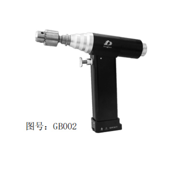
The precision of the drilled hole depends entirely on the concentricity of the spindle, which is directly influenced by the gear reducer's output shaft bearings. Standard ball bearings may suffice for rough carpentry, but precision metalworking requires angular contact bearings or tapered roller bearings capable of handling both radial and axial loads without deflection. Engineers must evaluate how the gear reducer housing supports these bearings. Furthermore, matching gear quality to the required precision is mandatory. Gears manufactured to high AGMA grades feature tighter tolerances, smoother surface finishes, and optimized tooth profiles. Lower-grade gears introduce micro-vibrations that translate directly into spindle runout, causing oversized or out-of-round holes.
Gear Architecture | Backlash Profile | Primary Strength | Ideal Application |
|---|---|---|---|
Planetary | Low (3-10 arcmin) | High torque density, inline footprint | Industrial machining, earth drilling |
Harmonic | Zero | Absolute precision, smooth motion | Surgical robotics, aerospace assembly |
Cycloidal | Very Low | Extreme shock load resistance | Heavy industrial, interrupted cutting |
Belt/Pulley | N/A (Flexible) | Vibration isolation, easy ratio changes | Stationary workshop drill presses |
Assessing the power-to-weight ratio is critical when designing handheld or robotic drilling equipment. Heavy gearboxes induce operator fatigue and exceed the payload capacities of robotic arms. Engineers balance the need for multi-stage reduction against physical space limitations. Achieving very low RPMs often requires stacking multiple gear stages. While a two-stage planetary gearbox provides massive reduction, it doubles the length and weight of the unit. Material selection plays a vital role here. Utilizing aerospace-grade aluminum housings and hollow-shaft designs mitigates weight penalties while maintaining structural rigidity. The physical envelope of the gear reducer must align with the ergonomic and spatial constraints of the final application.
Operating environments dictate strict compliance standards for gear reducer construction. In clinical settings, material selection is heavily regulated. Components must utilize medical-grade stainless steel or titanium to resist corrosion. Sealing requirements are paramount; the internal gearing must be hermetically sealed to withstand repeated high-temperature autoclaving without degrading the internal lubricants. Designing a low vibration medical drill requires navigating these strict sterilization protocols while maintaining zero-backlash performance. Conversely, industrial standards focus on IP ratings. Gearboxes operating in heavy machining environments require robust labyrinth seals and positive internal pressure to prevent the ingress of abrasive metallic dust, synthetic coolants, and cutting fluids.
Selecting a gear architecture involves a direct trade-off between financial investment and mechanical precision. Standard planetary gears provide low backlash suitable for most industrial applications at a reasonable price point. Moving from low backlash to true zero-backlash performance requires implementing harmonic drives, which introduces an exponential cost increase due to the complex manufacturing processes required for flexible splines. Engineering teams determine the acceptable threshold of radial play for their specific application. Specifying a zero-backlash harmonic drive for a standard structural steel drilling operation wastes capital, while utilizing a standard planetary gear in a neurosurgical device introduces unacceptable patient risk. Precision must align strictly with application requirements.
Maintenance protocols heavily influence gear reducer selection. Field-serviceable systems, such as belt and pulley configurations or accessible pull-gear reducers, allow operators to easily replace worn components, adjust tension, and replenish lubrication. This accessibility extends the operational life of the equipment but requires scheduled downtime and trained maintenance personnel. Hermetically sealed gearboxes offer a run-to-failure operational model. These units require zero maintenance, preventing contamination and eliminating the need for lubrication schedules. Once the internal bearings or gears fail, the entire unit requires replacement. Engineers weigh the operational downtime required for maintenance against the upfront cost and replacement logistics of sealed, continuous-duty gearboxes.
Gear friction at high torque loads generates significant localized heat. In continuous-duty slow drilling applications, this thermal buildup degrades lubrication viscosity and alters the dimensional tolerances of the metal gears, leading to premature wear and potential seizure. Mitigating thermal risks requires proactive engineering.
Specify synthetic lubricants engineered to maintain viscosity at elevated temperatures.
Integrate external heat sinks or active liquid cooling jackets into the gearbox housing to dissipate thermal energy.
Establish strict duty cycles based on empirical thermal modeling, ensuring the equipment has adequate time to cool between heavy drilling operations.
Poor alignment between the primary motor, the gearbox input shaft, and the final spindle introduces severe side-loading on the bearings. This misalignment causes premature bearing failure, excessive heat generation, and severe resonant vibration throughout the tool housing. Mitigation relies entirely on precision assembly protocols.
Utilize precision-machined mounting flanges to ensure absolute concentricity between mating components.
Implement flexible couplings between the motor and gearbox to absorb minor angular misalignments without transferring destructive forces to the gear teeth.
Conduct strict concentricity checks using dial indicators during the final assembly process to verify alignment tolerances.
Traditional gear lubrication relies on speed to function. The rotation of the gears pulls oil into the mesh, forming an elastohydrodynamic lubrication film that separates the metal teeth. At very low speeds, this film fails to form, causing destructive metal-to-metal contact and rapid galling. Mitigating this risk requires abandoning standard gear oils.
Select high-viscosity synthetic greases or solid lubricants containing molybdenum disulfide or PTFE.
Ensure these specialized compounds are engineered specifically for low-speed, high-pressure boundary lubrication.
Verify that a protective barrier remains between the gear teeth even when rotational speeds drop to near zero.
Achieving stability in a slow drill requires moving away from direct-drive motor throttling and implementing a mechanical gear reduction system tailored to the application's specific tolerance for backlash, vibration, and footprint constraints. Direct-drive systems simply cannot maintain the torque and rotational consistency required for precision low-speed operations. Shortlisting the correct architecture follows a clear logic: default to planetary gears for compact, high-torque industrial needs; mandate harmonic drives for zero-backlash surgical and medical applications; and utilize belt or pull gear speed reducers for cost-effective vibration isolation in stationary workshop setups.
Define the exact target RPM and torque requirements based on the specific materials being drilled.
Request certified backlash specifications and runout tolerances from gearbox manufacturers before procurement.
Conduct dynamic load testing on prototype assemblies to verify thermal dissipation and vibration performance under actual cutting loads.
Evaluate the operational environment to determine necessary IP ratings or medical sterilization compliance.
A: The ideal ratio depends entirely on the application. Workshop retrofits often use 2:1 to 4:1 ratios, while heavy industrial or earth drilling equipment requires 10:1, 13:1, or even 20:1 ratios to achieve the necessary torque amplification and speed reduction.
A: Gear reduction allows the motor to run at its optimal, stable speed while mechanically multiplying torque. This prevents the motor from stalling or cogging under load, ensuring consistent RPM and preventing micro-stutters at the drill bit.
A: A pull gear speed reducer is an auxiliary mechanical unit mounted to a machine's input shaft. It provides a reliable mechanical reduction to slow down legacy machinery, making it ideal for cost-effective upgrades on standard workshop drill presses.
A: Vibration typically stems from gear backlash, poor bearing concentricity, or resonant frequencies generated by improper gear meshing. Utilizing zero-backlash harmonic drives and precision angular contact bearings eliminates these vibrational sources.
A: No. A reduction kit slows the spindle speed and increases torque, but runout is dictated by the quality of the spindle bearings and the rigidity of the quill housing. Reduction kits isolate motor vibration but do not fix mechanical runout.
A: Planetary gears use multiple toothed gears rotating around a center sun gear, offering high torque in a compact inline design. Cycloidal drives use eccentric rolling motion against pins, providing superior shock load resistance and torsional stiffness.


